

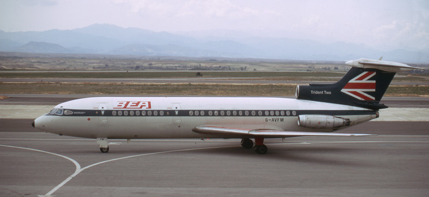
On visiting our Trident many people comment on the moving map display asking if it’s a kind of Sat Nav. The system on the Trident was designed long before GPS was available and indeed was one of the first stand alone navigation systems not requiring any ground stations or satellites to operate. This is how it all works.
Maurice Gatsonides. There’s a name you don’t often hear. Maurice was a 1950s Dutch rally driver who wanted to measure his speeds around the track and invented the Gatsometer, a radar speed gun. It was later developed to make his company very rich and annoy drivers around the world as the Gatso speed camera. What’s all this got to do with moving maps you ask, well the principle employed in Maurices’ gun was the same as on the moving map system fitted to the Trident, Doppler radar. The Doppler effect was not new. Austrian scientist Christian Doppler had given his name to it back in 1842.
He discovered there is a perceived change in frequency of a sound/radio wave to an observer who is moving relative to the wave source. This was known as Doppler Frequency shift or the Doppler effect. Like everything about the black art of radio/radar this sounds complicated.
A simple way to understand the principle is to think about the noise a train makes to a passenger standing on a platform as the train approaches and leaves the station. Approaching the passenger the sound waves bunch up and give an increasing frequency of sound, as it passes him and goes down the line the sound waves stretch out and he hears a reducing frequency of sound. Now if the train was replaced by a radio transmitter and the passenger replaced by a radio receiver and computer, it would be possible to measure the Doppler shift in the frequency of the transmitter and thus calculate the speed of its passing.
This is what a speed camera does to your car, it measures the reflected radio wave off the car as if that were the transmitter with the camera the receiver, a computer then calculates your speed and sends you the ticket! The Trident Doppler system does exactly the same measuring the relative speed between the aircraft and the ground. On the Trident the Doppler aerial, which acts as the transmitter and receiver, is mounted under the cabin floor ahead of the main undercarriage.
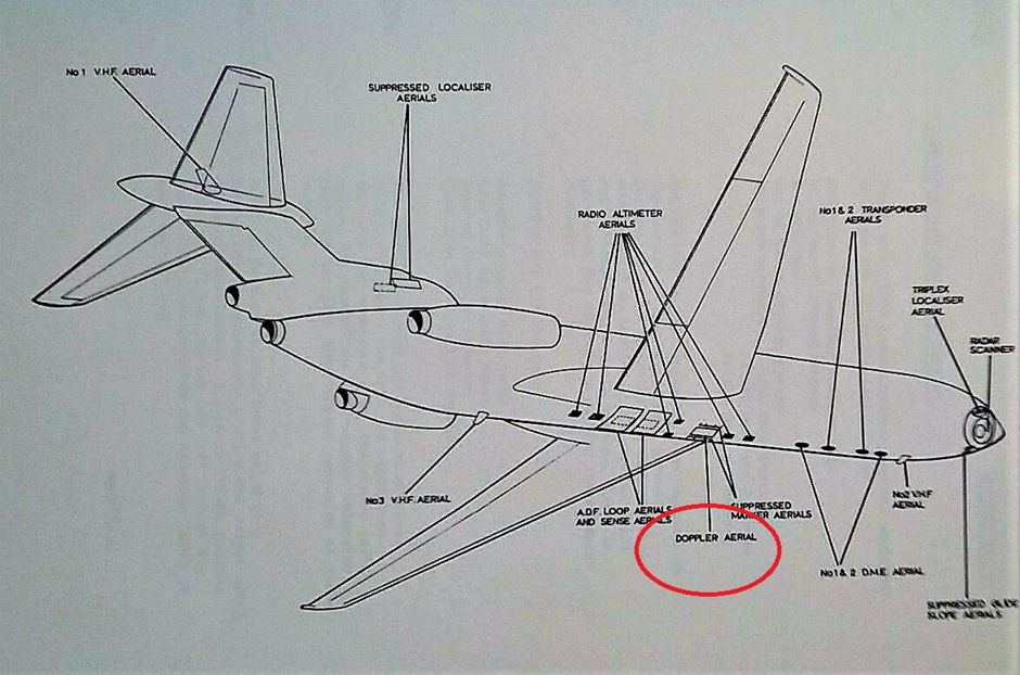
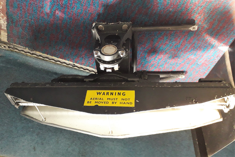
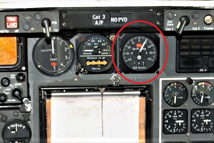
It is not a fixed aerial but is fitted in a mount that can rotate and move up and down. We will see why later. The information derived from the Doppler system is Ground speed and Drift angle.
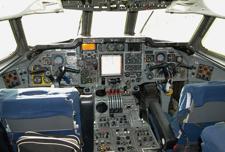
This is displayed to the pilot on an indicator fitted on the centre instrument panel and is also fed to the moving map computer. If the pilot is navigating by old-fashioned maps this information is very important to allow him to plot his position should there be any wind blowing the plane off the desired track.
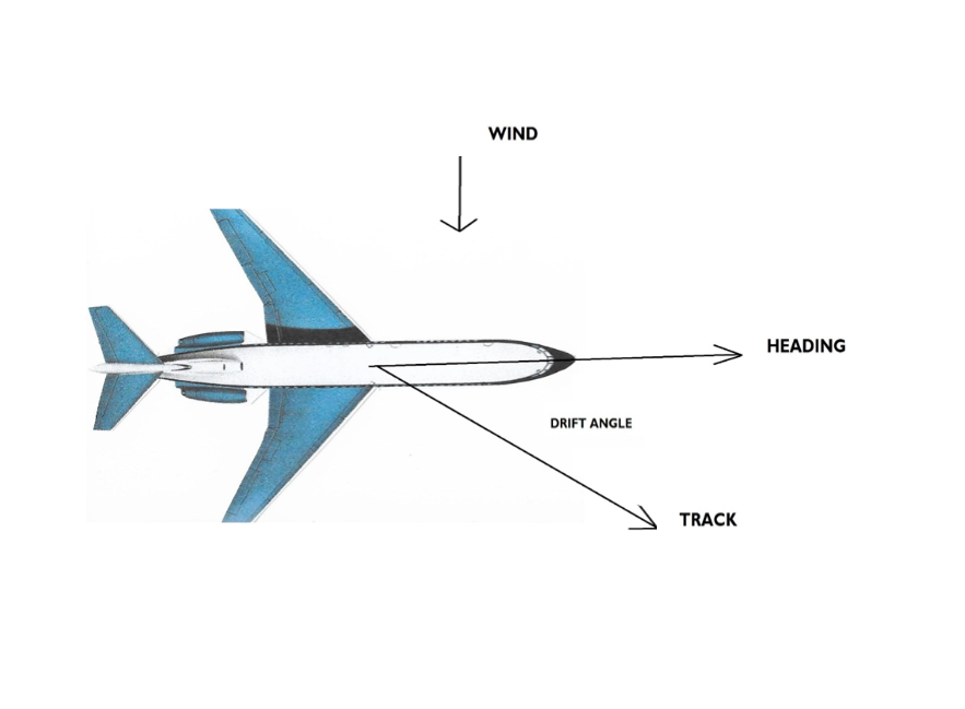
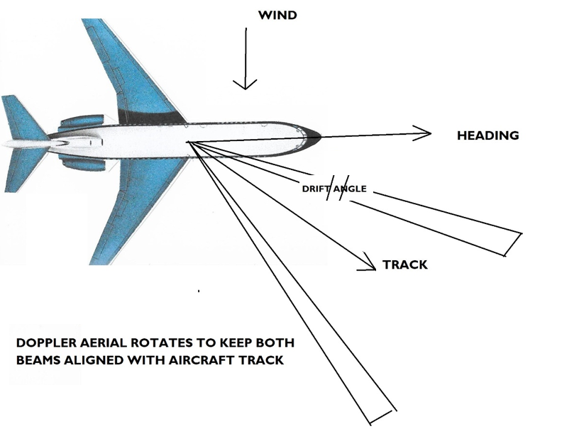
This basic ground speed and drift angle along with compass information can also be used by the doppler computer to drive the moving map to show the aircraft’s position. Ground speed is pretty obvious but what is drift angle? Simply stated, it’s the angle between the aircraft’s heading (the direction the nose is pointing) and the aircraft track (the direction in which the aircraft is actually moving). With no wind there would be no drift angle however any wind would start to push the aeroplane off its desired track despite the heading remaining the same. This would create a drift angle.
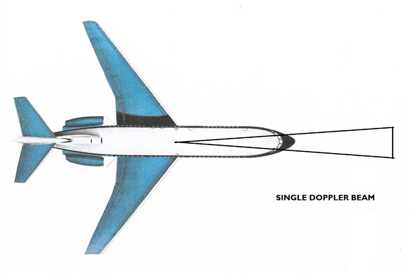
If there was no wind and our plane was flying along straight and level with our Doppler aerial transmitting a single signal ahead and down to earth, we can see, just like the Gatso camera, it would be able to measure the Doppler shift due to the relative movement between the earth and our aeroplane. This would then be calculated by the computer into a ground speed and fed to the cockpit display.
This would work fine as long as there was no wind causing a drift angle, if there was drift the Doppler beam would no longer be looking in the direction the aircraft is actually moving so an error in ground speed would occur. This problem was cleverly overcome by having two beams offset from the aircraft centre line. When there was no drift, both beams would have the same Doppler shift and the ground speed indication could be calibrated to read correctly. However, if the aircraft began to drift these two beams would each have a different frequency shift. This is where the moveable aerial comes in. The computer uses this difference to create an error signal which drives a motor to rotate the complete aerial assembly until the two beams once again have the same frequency shift. In reality this would align the aerial with the aircraft’s track, thus it can be seen the angle the aerial has been driven through is the actually the drift angle. That is how drift angle is calculated.
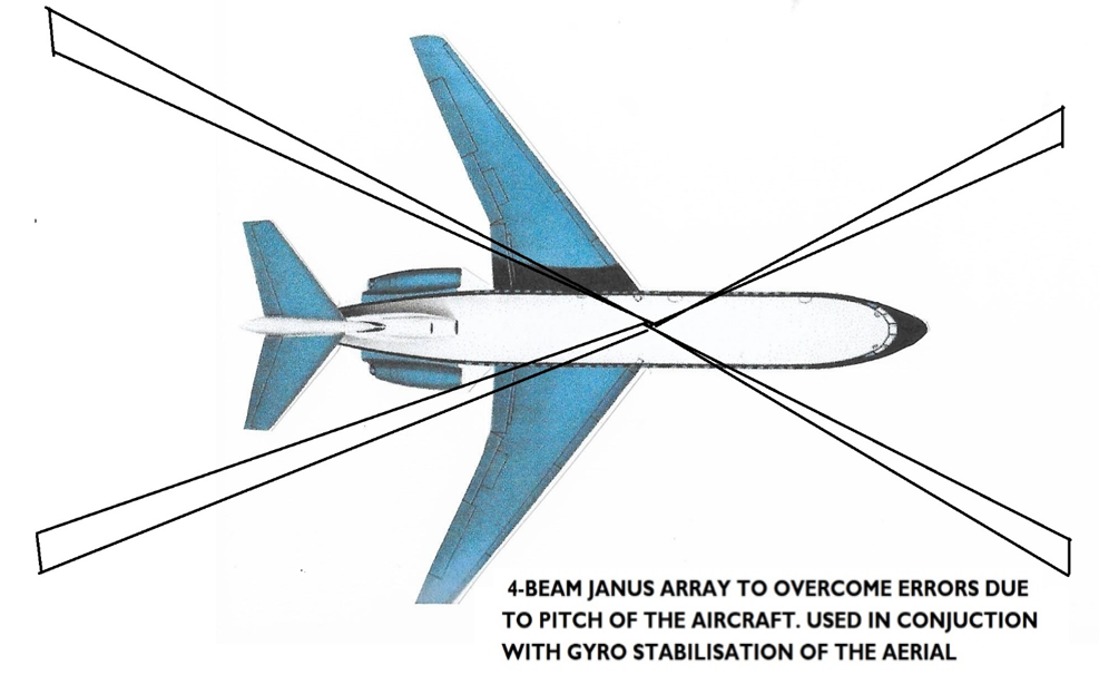
One final problem would be when the aeroplane climbs or dives as this would alter the position of the beams hitting the ground and again would give incorrect ground speed. This is overcome in two ways. One by gyro stabilising the aerial so it is always horizontal to the earth’s surface and secondly by adding another two beams, this time transmitting rearwards. The frequency shift of these are algebraically added to that of the front beams so as when the aircraft climbs the front beams go up as the back beams go down cancelling out any errors. This gives us the four beam Janus array. Named after Janus the Roman God of doorways who it was said could face both ways at once.
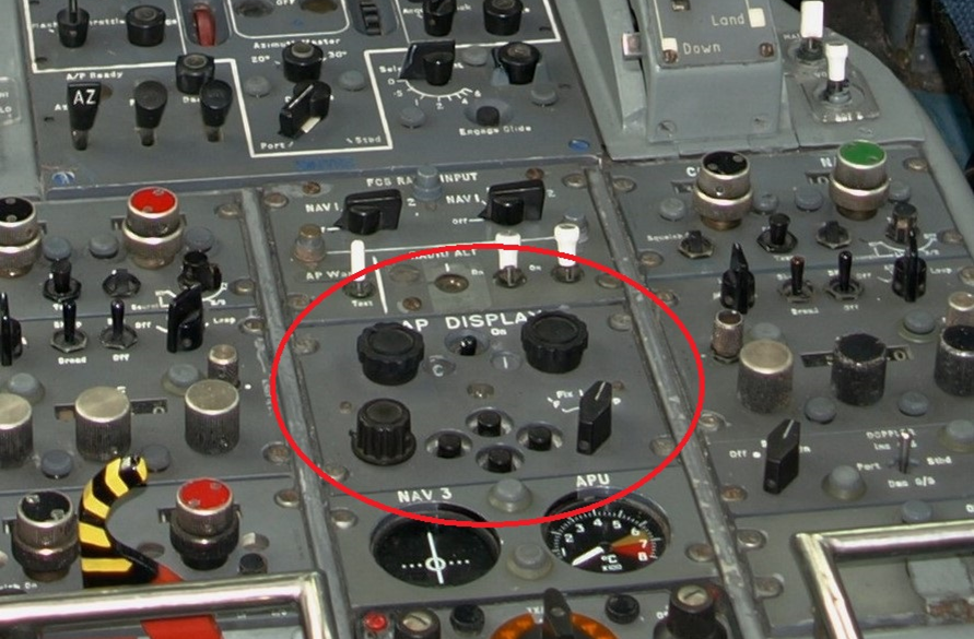
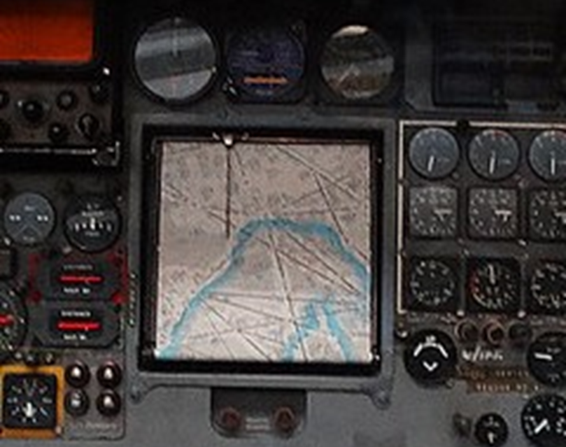
We now know how the system accurately computes our speed across the ground and any drift angle due to wind. If you know your speed and add time into the equation you can measure how far you have travelled. Thus if you also include compass information into the mix and you know where you started from, you can work out where you are at any one time. This is the principle of the moving map display. Before take off the crew would have to load a paper map roll of their route into the display unit. They would then use the control buttons on the pedestal to move the pointer over their departure point. From then on the Doppler system will calculate how far and in what direction they have moved from that point driving the map and pointer to display this information to the crew.
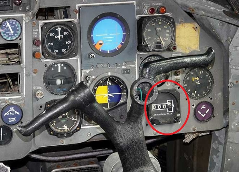
One final thing the Doppler system could do was to give a distance to go indication just like present day Sat Nav. The pilot would dial in the distance to his next waypoint on the indicator and the Doppler would slowly wind down the distance as the plane approached its destination. This indicator was fitted on the co-pilots panel only.
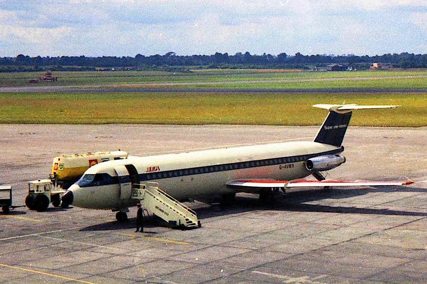
The Doppler and map combination were well ahead of their time when the Trident was developed as it was a self contained navigation system and could be used for either short or long routes. Most other aircraft at the time were fitted with the Decca navigator system which used a world wide series of ground stations to plot the aeroplanes position. This was fine for short range but long distance navigation was subject to errors due to the curvature of the earth. Decca was also a difficult system to set up and use. The BAC 1-11 used a moving map called HARCO, based on the Decca system to obtain its position.
As BEA mainly used their BAC 1-11s on the short internal German services this was not a problem. Bearing in mind at the time Germany was still divided and only British, American and French airlines could operate into West Berlin by flying over Eastern Germany in narrow air corridors. It was important to have an accurate navigation source to remain in these corridors and the Decca system was fine for these short flights. Later in the 1-11s life the map system was removed as the Decca chains were switched off as more modern and reliable equipment took over. The irony of all this is that the Doppler system on the Trident was built by the Decca Navigator company!
To sum up in a nutshell, we have four ‘speed cameras’ working together and mounted on a stable platform that is always aligned with the direction the aeroplane is going in, to give us drift angle and our speed across the ground. This is mixed in the map computer with time, compass information and where we started from to give our present position that is then displayed on the map. As we can see from this story the Trident not only led the way with its Autoland but with navigation systems as well, truly a remarkable aircraft.
‘till the next time Keith
Registered Charity No. 285809